 |
|
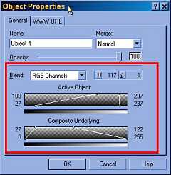
Figure
10. Blend Settings available from the Object Properties Dialogue.
|
Introduction.
The enhanced blend controls are really hot (Figure
10). Blend Settings are reached by selecting Object
Properties after either right clicking on an object or on its icon
in the Objects Docker.
Complete control of the blend
between both active and underlying objects can be adjusted over all
channels in great depth.
An example of the power of
this feature is shown in Figure 11.
Here the blend of one object with another is controlled for each RGB
channel by specifying the precise level of transparency and merge for
the full 256 colour range of each pixel in each channel. It is this
feature which greatly improves PP9's ability to deal with imported PhotoShop
files.
 |
|
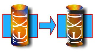
Figure
11. An example of using PP9's Blend Settings in the Object Properties
Dialogue. The image on the left is the original with two objects
- the blue rectangle (lower object) and the textured cylinder
(upper object). The belend was created using the settings shown
in Figure 10.
|
The two graphs shown in the
Object Blend portion of the Object Properties dialogue
box depict the blend controls of the Active Object (that currently
selected) and the Composite Underlying object's. Blend controls
are manipulated by dragging on the nodes on each graph. You can control
the blending of the entire RGB spectrum or the Red, Green or Blue channels
separately and in combination. The currently selected node appears as
a hollow circle, and the cursor changes to a cross-hair when near it
or unselected nodes which appear as filled black circles. You can also
drag on the graph itself to move the currently selected node.
Blend Settings Nodes.
You can drag any of the following nodes in either the Active or the
Underlying graphs:
- Increasing Maximum (top
left node)specifies the upper maximum grayscale value of the pixels
in the object
- Increasing Minimum (bottom
left node)specifies the upper minimum grayscale value of the pixels
in the object
- Decreasing Maximum (top
right node)specifies the lower maximum grayscale value of the pixels
in the object
- Decreasing Minimum (bottom
right node)specifies the lower minimum grayscale value of the pixels
in the object
The Blend Settings graphs
depict grayscale representations of the chosen channel. For the separate
Red Green and Blue channels, the representation is straight forward
with the grayscale value directly representing the equivalent colour
value from 0 to 255 for the colour intensity. However, with the combined
RGB channel the situation is somewhat more complex with some very different
colours having identical grayscale values.
 |
|
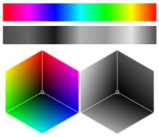
Figure
12. Grayscale representations of the colours in the combined RGB
channel.
|
My interpretation of the
situation is that the grayscale value represents the overall lightness
of the combined RGB colour. This is shown in Figure
12 where the very light yellows and cyans correspond to a
high grayscale value and the more intense / darker colours of blue and
to an extent red, correspond to the lower grayscale values.
The description of Object
Blends here is quite large and has been broken up into several sections.
Please go on to the next page to find out more about blends.
Continue
to Page 2 of the Object Blends section