Composite Underlying (Objects) Blend Adjustments
Overview:
Adjusting the nodes of the Composite Underlying graph alters the opacity/transparency
of the Active Object according to the colours in the objects beneath
it.
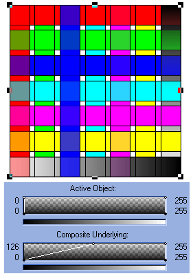
In the left panel below (Figure
23), the Increasing Maximum node of the Composite
Underlying setting has been dragged from 0 to a value of 126. This
has increased the transparency of parts of the upper object (the horizontal
lines) which are covering DARKER regions in the underlying object
(the vertical lines). Regions such as the blacker part of the vertical
grayscale bar and the blue and red vertical bars.
 |
|
Figure
23. Effect of altering the Increasing Maximum node of the
Composite Underlying object.
|
|
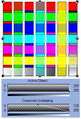 |
|
Figure
24. Effect of altering the Decreasing Maximum node of the
Composite Underlying object.
|
|
In the right panel above
(Figure 24), the Decreasing Maximum
node of the Composite Underlying object has been adjusted from
255 down to 126. This has caused an increase in transparency levels
in areas of the active object which are above LIGHTER regions
of the underlying object.
Note that all regions of
the upper (horizontal) object that are over white regions of the lower
(vertical) object are completely transparent. Regions of the upper object
above yellow or cyan regions of the lower object are semitransparent
while regions above dark colours such as blue are almost completely
opaque.
Note also the increasing
transparency of the upper horizontal bars as they approach the lighter
end of the underlying vertical grayscale bar.
 |
|
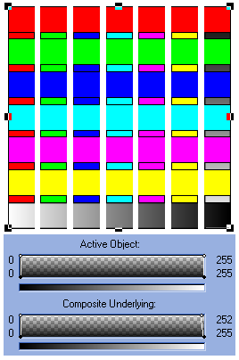
Figure
25. Small ajustments of the Decreasing Maximum node in the
Composite Underlying object completely elimiate white areas
in the Active Object.
|
|
 |
|
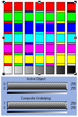
Figure
26. Small ajustments to both the Decreasing and Increasing
Maximum nodes of the Composite Underlying object completely
eliminates both black and white regions of the Active Object.
|
|
The effect following adjustment
to the Decreasing Maximum node (top right node) of the Composite
Underlying graph is extremely sensitive when any white regions occur
in the lower object. Even a shift of 1 or 2 points will render completely
transparent all areas of the upper object above white regions in the
lower object (Figure 25). The reverse
is also true. When the Increasing Maximum node (top left node) of the
Composite Underlying graph is a adjusted only a few points, any regions
in the upper object which are above dark areas of the lower object become
completely transparent !
A nice effect can be made
by adjusting both the Increasing and Decreasing Maximum nodes on the
Underlying Composite graph by a few points each. Then, regions in the
upper object above both very light and very dark regions of the
lower object become transparent (Figure 26,
above right).
Blends to Single Colour Channels.
Let us now look at adjustments
to the single colour channels in the Object Properties Blend Settings.
Adjustments to the single
colour channels are more straight forward than those to the combined
RGB channel. The Red, Green and Blue single colour channels are selected
from the dropdown 'Blend:' list. Furthermore, you can make changes
to each of the different channels that are available and the result
will depend on the cumulative changes made to all separate channels.
 |
|
Figure
27. Decreasing Maximum node changes to the RED channel of the
Active Object.
|
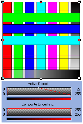
In the example shown in Figure
27, the Red Channel has been selected for manipulation.
The colour of the lines joining the nodes changes to the colour of the
selected channel and the lightness bar below each blend graph also changes
to a gradient from black to 100% of the colour of the selected channel
(in this case, red).
The Decreasing Maximum
node of the Active Object graph has been dragged down to 126
(about half way). All sections of the Active Object (the upper object
of horizontal bars) which contain bright red have been rendered transparent.
Therefore, as both the magenta and the yellow bars contain red (RGB:255,0,
255 and RGB:255,255, 0 respectively), both of these bars have been rendered
transparent. Note also the effect in the grayscale bar.
 |
|
Figure
28. Increasing Maximum node changes to the Red channel of the
active object.
|
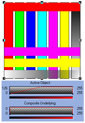
In the second example of
singular adjustments to the red channel (Figure
28), the Increasing Maximum node of the Active
Object graph has been dragged from 0 to 126. All objects WITHOUT
a degree of red up to 126 are now transparent. The effect also causes
the darker regions of the grayscale bar (upper object) to also be rendered
a degree of transparency.
 |
|
Figure
29. Increasing Maximum changes to the Composite Underlying Object
in the Red channel only. This causes sections of the lower object
to appear to be above sections of the upper object!
|
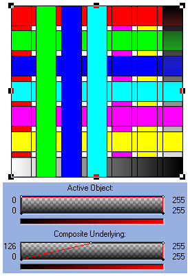
Finally, lets look at single
channel adjustments using the Composite Underlying (object) nodes.
In the third example (Figure 29,
left) the Increasing Maximum node of the Composite graph
has been dragged from 0 to 126.
This causes the Active (upper,
horizontal) Object to become transparent whenever there are regions
WITHOUT red in the underlying object.
This makes it so that some
parts of the underlying object (those vertical bars without red - such
as green, blue and cyan) appear to be ABOVE the upper object!.
Those areas of the lower object which contain red appear to remain underneath!
Now that's really cool
!
Continue
to Page 4 of the Object Blends section
